Warning: Improperly programming a GPU, or a display, may damage the devices.
This post demonstrates the effects of the triangle winding order on the render.
Preparation:
RPi vc4 GPU, by default, assumes CCW winding order as denoting the front-face
of a triangle. The GPU also assumes that the start of the frame-buffer holds
the bottom-left pixel of the render. Effectively, the GPU adheres to a
typical Cartesian coordinate system - the bottom-left corner is the origin, and
the Y coordinate increases as it moves up.
But, the display pipeline (crtc, encoder, connector, monitor) assumes a coordinate system where the top-left corner is considered to be the origin, and the Y coordinate increases as it moves down. This particular difference, in addition to the winding order of the triangles, requires a bit of care in order to accurately draw and display an image.
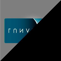
Suppose that one wants to display the 256x256
LunarG
image on a 256x256 frame-buffer. Below is the view GPU has of the
various coordinates of the square to be rendered:
ndc(-1,1,-1)                                ndc(1,1,-1)
scr(-128,128,0)                             (128,128,0)
tex(0, 1)                                   tex(1, 1)

                    ndc(0,0,-1)
                    scr(128,128,0)
                    tex(0.5, 0.5)

ndc(-1,-1,-1)                               ndc(1,-1,-1)
scr(-128,-128,0)                            (128,-128,0)
tex(0, 0)                                   tex(1, 0)
Since the GPU assumes CCW winding order as denoting the front-face of a
triangle, the vertices that we provide to the GPU are also in CCW order, as
shown below. These are viewport/screen coordinates, in 12.4 fixed-point
format, being provided to the GPU’s non-vertex-shading pipeline.
// {x, y, z, 1/wc, s, t}    //  NV-shader in-mem vertex format

{-2048, 2048, 0, 1, 0, 1},  //  TL
{-2048, -2048, 0, 1, 0, 0}, //  BL
{2048, -2048, 0, 1, 1, 0},  //  BR

{2048, -2048, 0, 1, 1, 0},  //  BR
{2048, 2048, 0, 1, 1, 1},   //  TR
{-2048, 2048, 0, 1, 0, 1},  //  TL
If the GPU is asked to render only the first triangle, (TL, BL, BR), and if
the frame-buffer as displayed by the monitor is captured, the image is:
Because of the disagreement between the GPU and the display about the frame-buffer’s orientation, the image seen is inverted. If the image is flipped vertically, the GPU’s view of the render emerges: the image is consistent with the Cartesian coordinate system inside of which the GPU renders.

Fix the inverted image:
There may be multiple ways to have the GPU’s output rendered in the ‘correct’ orientation as seen by a viewer.
The display pipeline may be requested to consider the start of the frame-buffer as the bottom-left corner of the display. Since the display circuitry (usually) refreshes the screen from top-to-bottom, it reads the frame-buffer from bottom-to-top, instead of the usual top-to-bottom.
Another option is to have the GPU render in the frame-buffer, an image which is the expected image flipped across the X-axis. Such a frame-buffer is ready for consumption by the display pipeline. The GPU does the job of flipping the image for us, so that the frame-buffer, as written by the GPU, has the top-row of the expected image at the start of the frame-buffer.
A way to have the GPU render an inverted image is to flip the sign of the
clip-space (or screen-space, if utilizing non-vertex-shading pipeline)
Y-coordinate of each vertex (Y-flip). This change is performed in the
vertex-shader.
But such a change to the Y-coordinate has the effect of reversing the winding order of the triangles.
If originally the vertices were specified with the CCW winding order, the
Configuration Bit named Clockwise Primitives must be set. After the
Y-flip, a front-facing triangle’s vertices gets ordered in CW
winding-order; without that bit set, the front-facing triangle will be
considered to be a back-facing one by the Primitive Processing stage.
If originally the vertices were specified with the CW winding order, the
Configuration Bit named Clockwise Primitives doesn’t need to be set.
After the Y-flip, a front-facing triangle’s vertices will be ordered in CCW
winding-order; the CCW winding-order is considered, by default
(i.e. when Clockwise Primitives bit is off) to denote front-facing
triangles.
Below is the setup, when specifying the vertices in the CW winding order, along with the Y-flip:
ndc(-1,1,-1)                                ndc(1,1,-1)
scr(-128,128,0)                             (128,128,0)
tex(0, 1)                                   tex(1, 1)

                    ndc(0,0,-1)
                    scr(128,128,0)
                    tex(0.5, 0.5)

ndc(-1,-1,-1)                               ndc(1,-1,-1)
scr(-128,-128,0)                            (128,-128,0)
tex(0, 0)                                   tex(1, 0)
The triangles specified in the CW winding order:
// {x, y, z, 1/wc, s, t},

{-2048, 2048, 0, 1, 0, 1},  //  TL
{2048, -2048, 0, 1, 1, 0},  //  BR
{-2048, -2048, 0, 1, 0, 0}, //  BL

{-2048, 2048, 0, 1, 0, 1},  //  TL
{2048, 2048, 0, 1, 1, 1},   //  TR
{2048, -2048, 0, 1, 1, 0},  //  BR
After the Y-flip (Note that the texture coordinates aren’t changed):
// {x, y, z, 1/wc, s, t},

{-2048, -2048, 0, 1, 0, 1}, //  TL
{2048, 2048, 0, 1, 1, 0},   //  BR
{-2048, 2048, 0, 1, 0, 0},  //  BL

{-2048, -2048, 0, 1, 0, 1}, //  TL
{2048, -2048, 0, 1, 1, 1},  //  TR
{2048, 2048, 0, 1, 1, 0},   //  BR
These Y-flipped coordinates are passed to the GPU; it is asked to render only
the first triangle (TL, BR, BL), and the result is an up-right image, as
expected: