Warning: Improperly programming a GPU, or a display, may damage the devices.
This post demonstrates utilizing an image as a texture, to add details to the surface of a square. The image is the one used here.
Preparation:
The texture image is a JPEG of size 512x512. Extract the raw pixels in R8G8B8A8 format (equivalent to ABGR32, or 0xaabbggrr):
$ convert -size 512x512 -depth 8 texture.jpg RBGA:texture.bin
$ xxd -i texture.bin
The demo doesn’t yet have image-loading capability, hence the help being
requested from xxd to convert the raw pixels into a C-style array that can be
easily inserted into the demo.
Although the texture can be utilized as it is, the graphics hardware is usually more efficient in working with tiles of pixels. The HD7350 supports a 2D tiling mode. Hence, the texture, which is currently in the rasterizer/scan-out order of rows of pixels, is first converted into the 2D-tiled format.
The parameters can be calculated as shown in the previous demo. For this 512x512 RGBA image, the tiling parameters are:
width = 512
height = 512
bpe = 4 (FMT_8_8_8_8)
#samples = 1

tile_split = 1KB
bank_width = 1
bank_height = 2
macro_tile_aspect = 2
The above divides the original image in macro-tiles 4x8 micro-tiles, with each micro-tile of size 8x8 pixels. The tiled-image has the same format as the tiled-frame-buffer seen in the previous demo.
In order to convert the image into a 2D-tiled-image, one can request the help of the DMA engine of the hardware. It can be configured to take the source buffer and write into a destination buffer in the format chosen by the tiling parameters shown above.
The converted, tiled image is the texture which the Pixel Shader (PS) samples from. The corresponding buffer is configured as a texture resource (similar to how one configures the vertex buffer). Since the buffer is in 2D-tiled format, the resource-definition-words contain the tiling parameters that describe the format.
Shaders:
The vertex definition now includes, for each of the three vertices of a square (the fourth vertex is automatically calculated), the X, Y, Z coordinates in the NDC space and the U, V coordinates in the texture space.
The PS now interpolates the U, V coordinates for the target pixel, and samples the texture at that location.
/* Vertex Shader */

/*vs_start:*/
0x00000003, 0x84c00000, /*0: c.fs fs_start b;*/
0x0000a03c, 0x95000688, /*1: c.xd.pos(1) [60], r1 b;*/
0x00014000, 0x95200688, /*2: c.xd.prm(1) [0], r2 b,eop;*/

/*fs_start:*/
0x00000006, 0x80800400, /*3: c.vc(2) cc.a vfc_start b;*/
0x00000000, 0x85000000, /*4: c.ret b;*/
0x00000000, 0x00000000, /*5: c.nop;*/

/*vfc_start:*/
0x00001f01, 0x4c151090, 0x00000000, 0x00000000,
/*6: v.sem 0x90, flt3, -n, fs[0x1f][0].xyz1, r0;*/

0x00001f01, 0x479f9092, 0x0000000c, 0x00000000,
/*8: v.sem 0x92, flt2, -n, fs[0x1f][0xc].xy__, r0;*/
/* Pixel Shader */

/*ps_start:*/
0x00000004, 0xa00c0000, /*0: c.alu(4) alu_start b;*/
0x00000008, 0x80400000, /*1: c.tc(1) tc_start b;*/
0x00010000, 0x95200688, /*2: c.xd.pix(1) [0],r2.xyzw b,eop;*/
0x00000000, 0x00000000, /*3: c.nop;*/

/*alu_start:*/
0x00380400, 0x00346b10, /*4: a.ixy r1.x, r0.y, p0 210;*/
0x00380000, 0x20346b10, /*5: a.ixy r1.y, r0.x, p0 210;*/
0x00380400, 0x40146b00, /*6: a.ixy -.z, r0.y, p0 210;*/
0x80380000, 0x60146b00, /*7: a.ixy -.w, r0.x, p0 210,last;*/

/*tc_start:*/
0x00011e10, 0xf00d1002, 0xfc800000, 0x00000000,
/*8: t.samp r2, ps[0][0x1e][r1.xy__] xn,yn,zn,wn;*/
The raw command buffers are attached here and here. The former is the command buffer sent to the DMA ring of the hardware, in order to convert the texture image from RGBA to 2D-tiled format. The latter is the render command buffer sent to the GFX ring to render the square.
The vertices are defined as shown below. Note that the width of the square in NDC space is adjusted to have an actual square (and not a wide rectangle) on the 1280x720 display.
/* OpenGL NDC coords for a square */
static const float verts[] = {
	/* vtx coords */	/* tex coords */
	-0.5625, -1.0, 0,	0, 0,	/* BL */
	-0.5625,  1.0, 0,	0, 1,	/* TL */
	0.5625, -1.0, 0,	1, 0,	/* BR */
};
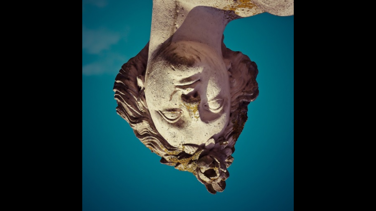
Output:
The image, as displayed on the previously cleared (to Black color) frame-buffer is, here.
The reason the image is inverted is that, for OpenGL, V (the vertical, or Y) coordinate is 0 at the bottom of the texture image, not at the top.
One can refer to the vertices definition above to verify that corner of the NDC-square that ends up at the top-left of the ViewPort-square is the one marked as bottom-left in the NDC space (The Y-axis is flipped during the ViewPort Transformation), and is also the one that has the (0,0) texture coordinates. Thus, the bottom-left corner of the texture image gets applied to the top-left corner of the ViewPort-square, resulting in a flipped image on the ViewPort. The remedy is to flip the V-axis of the source image being used as the texture. See also here.