Warning: Improperly programming a GPU, or a display, may damage the devices.
This post demonstrates the HD7350 support for MSAA rendering, through the use of Color Mask and Fragment Mask, the former of which facilitates Fast Clear of a render surface, and the latter, allows drawing on compressed MSAA surfaces.
Color Mask:
The Color Mask, or CMask, is a buffer, of size corresponding to the size of the target surface to which it is attached, which allows the GPU to mark the target surface as clear, without having to actually write the pixels on to the target surface. The state of the control bits stored in the CMask buffer allows the GPU to mark corresponding regions of the target surface as clear.
The actual clearing can be forced, or be done by the GPU automatically when rendering.
The process of performing the actual clearing of the surface is called
Eliminating the Fast Clear. It also has a corresponding render mode,
CB_ELIMINATE_FAST_CLEAR, for when one wants to force the elimination.
The calculation of the size of the buffer depends on the CMask Cache, the number of tile-pipes, and the size of the target surface.
The CMask facility supports storing 4-bits of control information per micro-tile of 8x8 pixels.
The number of tile-pipes on HD7350 is 2. The CMask cache size is 1024 bits per tile-pipe. Hence, the CMask cache is of size 1024 x 2 / 8 = 256 bytes.
The CMask facility works with micro-tiles of 8x8 pixels, and with macro-tiles of 128x128 pixels. A macro-tile can also be described as consisting of 16x16 micro-tiles. A macro-tile is thus capable of storing control information for 256 micro-tiles. Therefore, a macro-tile consumes 256 x 4 / 8 = 128 bytes.
Given that the CMask cache is 256 bytes total, one can fit two macro-tiles side-by-side in 2x1 pattern (width = 2 macro-tiles and height = 1 macro-tile).
Thus, the CMask cache can accommodate control information for 256x128 pixels at a time. The target surface, to which the CMask buffer will become attached, must have its dimensions aligned to the dimensions of the CMask cache (i.e. to 256x128 pixels). A 1280x720 resolution has its width of 1280 pixels already aligned to the CMask cache width of 256 pixels, since 1280 / 256 = 5 exactly. But the height of 720 pixels isn’t; it is aligned to the next higher multiple of 128 pixels, to 768 pixels.
Thus, for the calculation of the size of the CMask buffer, the effective resolution of the target surface is considered to be 1280x768 pixels.
The number of macro-tiles on the surface is:
(1280 x 768) / (128 x 128) = 60. This also means that the macro-tiles are numbered in the integer range [0, 59].
Each macro-tile consumes 128 bytes; 60 of them need a total of 60 x 128 = 7680 bytes of CMask buffer.
The alignment of the buffer depends on the Video DRAM’s GroupSize (256 bytes on HD7350) and on the number of tile-pipes (2 on HD7350); specifically on their product, here 2 x 256 = 512 bytes.
The registers CB_COLOR#_CMASK and CB_COLOR#_CMASK_SLICE are filled in
appropriately. The Fast Clear of the target surface can now be done by clearing
the CMask buffer to all zeroes; this can be achieved (as shown by the command
buffers extracted out of MESA) by asking the GPU’s GFX ring to DMA a constant
value of 0 into the buffer. The Clear Color is stored in another set of
registers, CB_COLOR#_CLEAR_WORD0 for RGB clearing, and
CB_COLOR#_CLEAR_WORD1 for clearing the Alpha component.
Fragment Mask:
The Fragment Mask, or the FMask, is a 2D-tiled, and compressed, MSAA surface. The FMask buffer is rendered into by the draw commands, and finally, it is resolved into a point-sampled surface for display. The resolving also automatically eliminates any fast-cleared tiles.
To determine the configuration for the FMask buffer, we must first calculate the configuration for the uncompressed, 2D-tiled surface of the target resolution. Note that this surface isn’t actually allocated any memory; only its configuration is calculated and made use of.
The FMask buffer is configured and allocated appropriately. Another buffer, corresponding to the point-sampled surface into which the FMask buffer will be resolved, must also be configured and allocated.
The configuration again depends on micro-tiles and macro-tiles, though the dimensions may differ from those in CMask configuration.
MESA first selects the best possible configuration of parameters for the MSAA surface. The parameters are:
tile-split: The number of bytes stored contiguously, per micro-tile.bankw: The number of micro-tiles in the horizontal direction, per macro-tile.bankh: The number of micro-tiles in the vertical direction, per macro-tile.mtilea: Balanced aspect ratio for a single macro-tile, taking into consideration the number of tile-pipes and the number of banks.
The default tile-split is set to 1024 bytes. For a surface with 4 bytes per
sample color and 8 samples per pixel, a micro-tile of 8x8 pixels consumes
8 x 8 x 4 x 8 = 2048 bytes. This is larger that default tile-split.
In such a case, MESA selects 8 x 8 x 4 x 2 = 512 bytes as the optimal
tile-split value. Note that a micro-tile still remains 8x8 in size;
each micro-tile can be thought of as being split into micro-splices,
each such splice of size 4x4 pixels, since 4 x 4 x 4 x 8 = 512 bytes, the same
as tile-split. But the majority of the calculations (save for the one that
calculates the total size of the MSAA buffer) works with micro-tiles.
Clearly, a single micro-tile of 2048 bytes more than covers a 512-bytes region.
So bankh = bankw = 1. But these calculations are per-tile-pipe and per-bank.
The HD7350 has 2 tile-pipes and 8 banks. The tiling of a single macro-tile can
be seen as below, where ut = a single micro-tile:
# A single macro-tile, where ut = one micro-tile. The columns represent each of
the two pipes, and the rows, each of the 8 DRAM banks.

ut ut
ut ut
ut ut
ut ut
ut ut
ut ut
ut ut
ut ut
The h-over-w aspect ratio is 8 / 2 = 4. That is, there are 4 micro-tiles in the
vertical direction, for a single micro-tile in the horizontal direction.
Because a portion of an image is to be mapped directly over this configuration, the tiling is adjusted to be more balanced, to be less skewed in one direction over the other.
The mtilea aspect ratio is set to sqrt(h-over-w), rounded up to the immediate
power of 2. This reduces the number of micro-tiles in the vertical direction,
per single micro-tile in the horizontal direction, while still keeping the
number of micro-tiles in the macro-tiles the same. That is, it does the
balancing of the aspect ratio.
The above tiling has 2 x 8 = 16 micro-tiles, per macro-tile.
With mtilea = 2, the new tiling assigns 2 micro-tiles vertically per
micro-tile assigned horizontally.
Suppose w and h are the dimensions of the
new tiling; then, w x h = 16, and h / w = 2. That results in 2 x w x w = 16, or
w x w = 8, or w = 2 x sqrt(2). Then, h = 4 x sqrt(2). Since w and h must be
powers of 2, we set w to be the closest power of 2, larger than w. This sets w
to 4, and thus, h to 16 / 4 = 4. That is, although mtilea = 2, the effective
aspect ratio of a macro-tile becomes 1.
# A single macro-tile, where ut = one micro-tile.

ut ut   ut ut
ut ut   ut ut
ut ut   ut ut
ut ut   ut ut
The units of alignment is thus 4 x 8 = 32 pixels, in both the horizontal and vertical dimensions. A resolution of 1280x720 is adjusted to be of 1280x736. The pitch of the MSAA-8x surface is, thus, 1280 x 4 x 8 = 40960 bytes. The entire surface needs 1280 x 736 x 4 x 8 = 30146560 bytes of storage. Note again that this MSAA surface isn’t actually allocated; a much smaller FMask surface is.
Based on the above calculations, allocate an FMask buffer. The FMask buffer contains 4-bit elements per sample. The VK_AMD_shader_fragment_mask article has some details.
An MSAA-8x surface thus needs 4 x 8 = 32 bits = 4 bytes of storage, per pixel, in its FMask surface. That is, the FMask surface can be considered as a point-sampled surface with 4 bytes per pixel.
Therefore, a similar calculation done above must be repeated with these new
parameters. The bankh, bankw, tile-split and mtilea parameters are copied from
the previous calculations - the tiling of the FMask surface must correspond to
that of the MSAA surface it is attached to.
Thus, bankw = bankh = 1, mtilea = 2, and tile-split = 512. A single macro-tile
is arranged as before:
# A single macro-tile, where ut = one micro-tile.

ut ut   ut ut
ut ut   ut ut
ut ut   ut ut
ut ut   ut ut
Each micro-tile is of size 8 x 8 x 4 x 1 = 256 bytes. The FMask buffer for an MSAA surface of 1280x736 resolution, therefore, needs 1280 x 736 / 64 = 14720 micro-tiles, or 14720 x 256 = 3768320 bytes, 8 times smaller than an uncompressed, MSAA-8x buffer of the same dimensions.
The FMask buffer must also be aligned at the boundary defined by the size of a single macro-tile. A single macro-tile is of size 4 x 4 x 256 = 4KB.
A second surface, which should be a point-sampled surface of appropriate configuration, must also be allocated to act as the destination for the MSAA-resolve operation performed over the FMask surface.
The surface is 1280x720 in dimensions, 4 bytes per sample and 1 sample per pixel.
Based on these parameters, a micro-tile turns out to be of size 8 x 8 x 4 x 1 =
256 bytes, resulting in tile-split = 1024, bankw = 1, bankh = 2,
h-over-w = 2 x 8 / (1 x 2) = 8, and therefore, mtilea = 2.
The initial macro-tile arrangement is:
# A single macro-tile, where ut = one micro-tile.

ut ut
ut ut

ut ut
ut ut

ut ut
ut ut

ut ut
ut ut

ut ut
ut ut

ut ut
ut ut

ut ut
ut ut

ut ut
ut ut
Since mtilea = 2, let w x h = 2 x 16 = 32, and h / w = 2. Then, 2 x w x w = 32,
and w = 4, with h = 32 / 4 = 8. The new, and balanced, macro-tile arrangement
is:
# A single macro-tile, where ut = one micro-tile.

ut ut    ut ut
ut ut    ut ut
ut ut    ut ut
ut ut    ut ut
ut ut    ut ut
ut ut    ut ut
ut ut    ut ut
ut ut    ut ut
The surface must therefore be aligned to 32x64 pixels. A resolution of 1280x720 is thus adjusted to 1280x768.
Frame-Buffer Tiling:
The point-sampled output surface is tiled; the colors stored in the corresponding buffer are not in the typical rasterization/scan layout. The 2D tiling chosen above consists of micro-tiles of size 8x8 pixels, and macro-tiles of size 4x8 micro-tiles, or 32x64 pixels. The ordering of pixels within a micro-tile, and the ordering of micro-tiles within a macro-tile are not linear, so as to benefit from the locality-of-reference and thereby from improved cache usage.
The pixels contained in a micro-tile, and the micro-tiles contained in a macro-tile are all stored in contiguous memory locations.
Consider a micro-tile of 8x8 pixels. In the configuration described above for the point-sampled surface, each micro-tile is 256 bytes in length, aligned at its natural boundary in the surface’s buffer.
Name the pixels from 0 to 63 as arranged consecutively in the buffer.
Then, the rasterization of the micro-tile can be described as below. Note that
this pattern depends on bankw, bankh and mtilea parameters, among others.
Any change in those parameters likely changes the ordering of pixels and
micro-tiles.
 0  1  2  3  8  9 10 11
 4  5  6  7 12 13 14 15

16 17 18 19 24 25 26 27
20 21 22 23 28 29 30 31

32 33 34 35 40 41 42 43
36 37 38 39 44 45 46 47

48 49 50 51 56 57 58 59
52 53 54 55 60 61 62 63
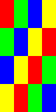
As an e.g., below is a single micro-tile as seen in the raw buffer for the point-sampled surface. Each square represents a single pixel. The pixels are consecutively numbered, 0 being the left-most pixel and 63 being the right-most.

After re-arranging the pixels as shown in the table above, the image that appears is:

This is the micro-tile that happens to contain the bottom-right corner of the triangle being displayed.
The tiling of micro-tiles within a macro-tile is more complicated; the pattern depends on the row and column parameters for each micro-tile. For the configuration setup in this post, below is the description of the tiling.
Label each micro-tile in a macro-tile from 0 to 31 in consecutive memory locations. It is re-arranged as shown below, depending on its position in the buffer.
Row % 2 == 0

   Col % 4 == 0    Col % 4 == 1    Col % 4 == 2    Col % 4 == 3
-+ ------------    ------------    ------------    ------------
0|  0  1  2  3      4  5  6  7      8  9 10 11     12 13 14 15
1| 17 16 19 18     21 20 23 22     25 24 27 26     29 28 31 30
2|  8  9 10 11     12 13 14 15      0  1  2  3      4  5  6  7
3| 25 24 27 26     29 28 31 30     17 16 19 18     21 20 23 22
4|  4  5  6  7      0  1  2  3     12 13 14 15      8  9 10 11
5| 21 20 23 22     17 16 19 18     29 28 31 30     25 24 27 26
6| 12 13 14 15      8  9 10 11      4  5  6  7      0  1  2  3
7| 29 28 31 30     25 24 27 26     21 20 23 22     17 16 19 18
Row % 2 == 1

   Col % 4 == 0    Col % 4 == 1    Col % 4 == 2    Col % 4 == 3
-+ ------------    ------------    ------------    ------------
0|  6  7  4  5      2  3  0  1     14 15 12 13     10 11  8  9
1| 23 22 21 20     19 18 17 16     31 30 29 28     27 26 25 24
2| 14 15 12 13     10 11  8  9      6  7  4  5      2  3  0  1
3| 31 30 29 28     27 26 25 24     23 22 21 20     19 18 17 16
4|  2  3  0  1      6  7  4  5     10 11  8  9     14 15 12 13
5| 19 18 17 16     23 22 21 20     27 26 25 24     31 30 29 28
6| 10 11  8  9     14 15 12 13      2  3  0  1      6  7  4  5
7| 27 26 25 24     31 30 29 28     19 18 17 16     23 22 21 20
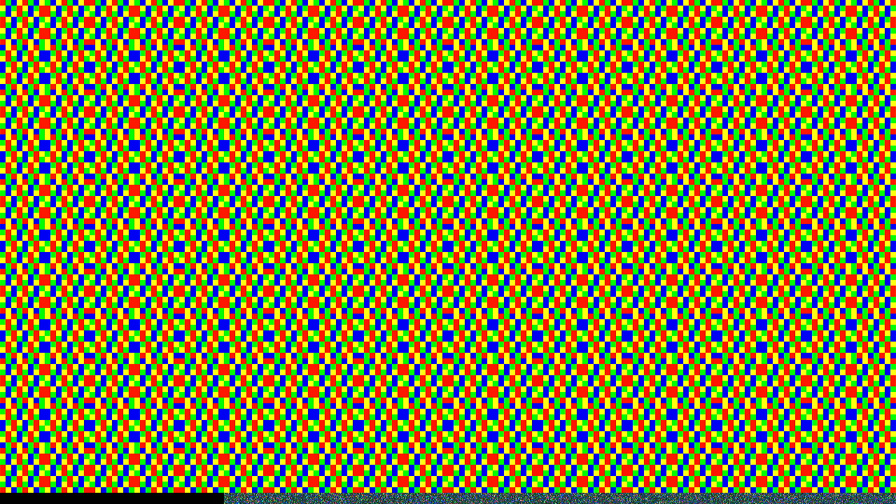
As an e.g., consider filling the macro-tiles of the frame-buffer with repeated copies of this basic macro-tile:
The frame-buffer, as displayed on the screen, looks like this image. Note that the image was captured from the OBS Studio software; it is likely to be a processed image.
Since a 720p vertical component of the resolution isn’t exactly divisible by 64, only 11 x 40 = 440 macro-tiles have been filled; the last 16 scan-lines would form only a part of the corresponding macro-tiles; those tiles were not filled in.
The image also shows that when the GPU has been setup for 2D tiling as described earlier, writing 1280 x 720 x 4 = 3686400 bytes of content (for e.g. the color Black) into the frame buffer does not necessarily mean that the entire frame buffer is written to.
Writing 1280x720 pixels, one after the other as if they are all arranged linearly, fully fills only 11 rows of 40 macro-tiles. That corresponds to 1280x704 resolution, and consumes 1280 x 704 x 4 = 3604480 bytes. Beginning at pixel row 704, writing the rest of the 3686400 - 3604480 = 81920 bytes, or 1280 x 16 = 20480 pixels, writes outside of the displayable region, into 10 macro-tiles. The rest 30 macro-tiles of the last row are left untouched.
That can be verified by noticing that a quarter of each of those 10 macro-tiles (i.e. the visible region of those macro-tiles) is colored Black. The black region is exactly 320 pixels wide, corresponding to the 10 partially visible macro-tiles. The region at and beyond pixel column 320 contains uninitialized/garbage data.
Writing 1280 x 720 pixels, when the frame-buffer and the GPU are setup for a Linear frame-buffer arrangement fills the buffer as expected.
When the frame-buffer has been setup as described earlier, for 2D tiling, there are 40 x 12 = 480 macro-tiles in total, of which the last 40 are only partially visible, but still claim memory space. The calculations around the sizes of various surfaces do consider this point.
Output:
The demo needs to fill in the CMask and FMask parameters into the appropriate
Color Control registers. Moreover, it also needs to create another rendering
command, that of drawing over the entire rectangular, point-sampled, output
surface in order to force the GPU to resolve (CB_RESOLVE) the MSAA
multi-sampled surface.
The raw contents of the point-sampled, output surface/buffer, are here.
Turning it into an image through the convert command,
convert -define png:compression-filter=0 -size=1280x768 -depth 8 BGRA:eg.1.bin eg.6.png, results in this image.
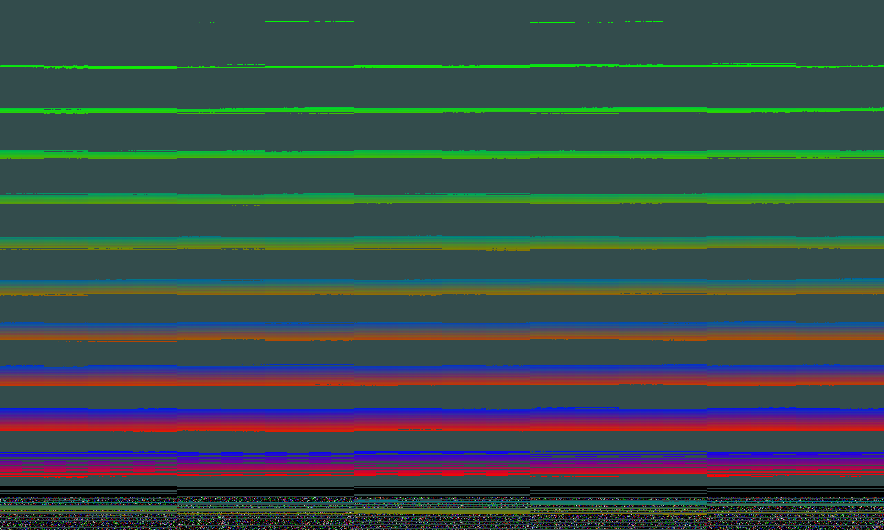
Since the frame-buffer is in 2D tiling mode, the raw contents of the buffer do not directly form the expected triangle, although one can indeed see some patterns.
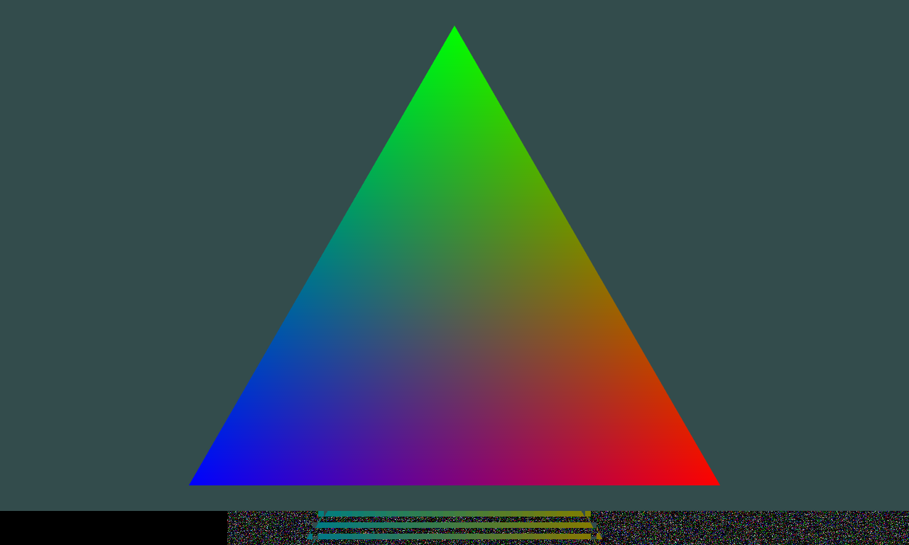
One can write a program
to take the raw contents
of the output surface, rearrange its pixels based on the tiling rules,
and output another raw image which, once converted to a displayable format
like PNG, shows the expected triangle. Opening it in an
image-viewer (for instance, feh --force-aliasing) which can disable its own
anti-aliasing support, allows one to see the MSAA 8x effects on the triangle.
[Note that the display resolution is 1280x720, but these images are 1280x768, to show the full contents of all the tiles, including those which are partial.]